Advanced Ultrasonic technique used for flaw detection, sizing, and imaging.
Allows for electrical manipulation of probe characteristics by introducing time shifts to sent and received signals.
Utilizes multi-element (array) probes for increased capabilities over conventional Ultrasonic’s.
Corrosion Mapping:
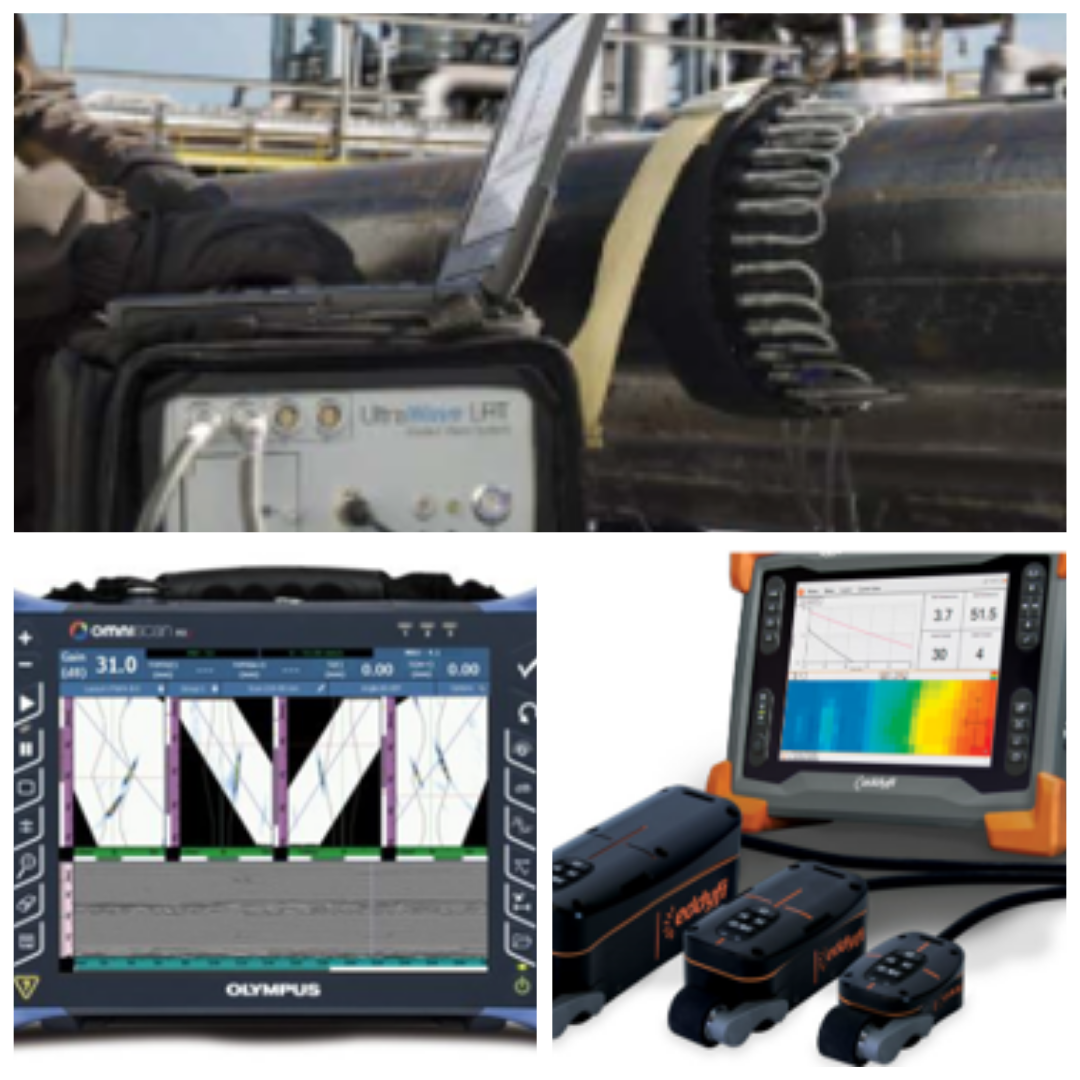
Guided Waves – LRUT
What is Guided waves? It is a long range ultrasonic inspection technique for the inspection of typically long pipes. Guided waves travel long distances along the pipe reaching up to 100m in a pulse echo configuration and depending very much on potential attenuation causing obstacles. Travel range can be also very short around 5m.
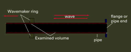
Ring with ultrasonic probes is clamped around pipe
Ring generates Low frequency ultrasonics around pipe circumference
Waves travel down the pipe
Sound reflects features in the pipe (e.g. Weld, Supports, Flanges and Corrosion)
Corrosion Mapping:
Pulsed Eddy Current – PEC
Screening tool based on Pulsed Eddy Current principle
Detection of remaining Average Wall Thickness (AWT)
No contact needed for the measurement
No special surface preparation needed
Measurement through insulation, concrete, coating, marine growth
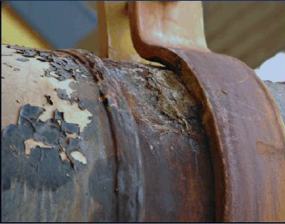
Corrosion under Support:
Corrosion under pipe supports (CUPS) is an area of concern in the industry It leads to loss of containment. A number of in-service leaks and ruptures have been attributed to this type of degradation Known limitations of visual inspections: – Visual inspection can provide an indication of corrosion (product build-up, rust staining) – but visual inspections are significantly hampered by the lack of access to the critical areas – and some cases may have corrosion present without any external visible indicators
Visual examination is needed and has to include:
Constant load supports out of adjustment
Shoes off support
Hanger distortion/damage
Bottomed out springs
Brace distortion/damage
Loose brackets
Slide plates/rollers
Corrosion under Support:
Short/Medium Range UT (SRUT/MRUT)
Short-Range Guided Wave is a technique which uses low frequency sound waves to flood the wall thickness of a pipe or a plate, and then reflect back at interfaces such as cracking or corrosion/pitting. A standard ½” near field probe allows for corrosion and defect inspection in limited space and close proximity situations. This technique is to be used as a screening tool only as remaining wall thickness measurements cannot be achieved. However, reflection distance can be measured with precise accuracy.
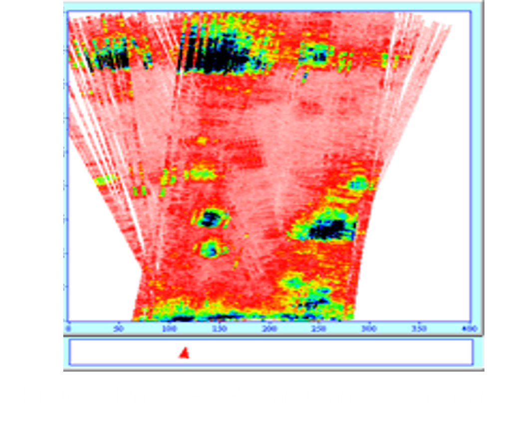
The short range guided wave technique uses a modified B-Scan graph but displays information in terms of “Plan View” using surface distance calculations. This technology can detect, image, record amplitude, size, and record X-Y location of corrosion and /or various defects
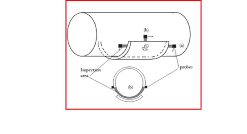
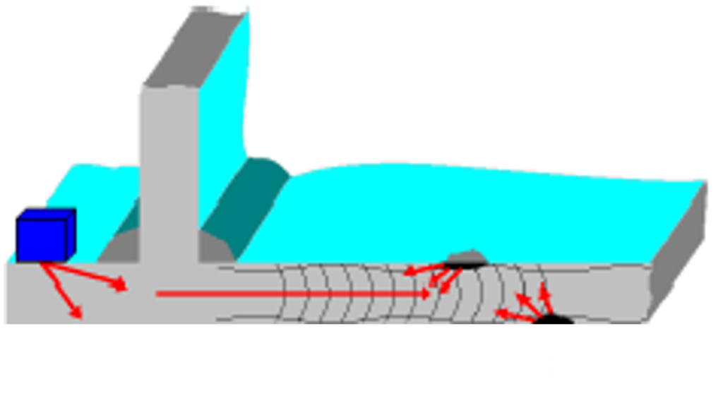
Technique:
Figure one depicts the transducer placement on the chime plate propagating short range ultrasonic waves into the annular plate. Figure 2 shows the set up when inspecting under pipe supports. The sound reflects at top side or underside corrosion providing a c-scan image of the defect. The signal strength at the defect provides evidence of the depth and overall morphology of the defects. Figure three provides a visual presentation of the collected data providing distance inspected, with of inspection along with details on the indications identified. Limitations include the lack of Top or Bottom Side Differentiation and the need for a 2 inch clearance for Probe Placement